1.What causes land drainage problems – the principles of water movement in soils
Whilst the effect of a functioning land drainage scheme can be observed by all, a basic understanding of the physical principles which govern this process enables the observer to both assess the effectiveness of a land-drainage scheme and also to appreciate why inappropriately or poorly designed drainage schemes fail to work.
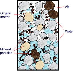
Figure 1 A diagram depicting a microscopic view of soil
The key to all of the following discussion is to understand what makes up a rootzone. The key ingredients are:
1.Mineral particles (sand,silt,clay)
2.Water
3.Air
4. Organic matter
Consider for example the soil rootzone represented in Figure 1, mineral and organic particles are locked together to form the solid fraction of the soil, whilst the pores (the spaces between the solid particles) are occupied by either soil water or soil air. The combination of solids, water and air is critical for not only plant growth, turfgrasses need all three components, but also surface strength.
1.1 Sports surface strength and soil moisture content
The resistance of a football pitch to wear by players and the ability of a pitch to provide a stable platform for quality football is highly dependent upon the turfgrass and the soil in which it grows. The grass plant provides a cushioned surface, with natural lubrication to reduce skin abrasion – its root network also provides a core structural function. The soil not only provides an anchorage for the grass plant but it is also the key load bearing component. The two components combined (grass and soil), must be of sufficient strength to resist damage from repeated use – both from running and sliding, but not of excessive strength so as to cause impact or musculoskeletal damage.
 Figure 2 The effect of soil moisture content and bulk density on rootzone strength. As moisture content increases, surface strength initially increases but then rapidly decreases. As bulk density increases from Bulk density 1 to Bulk density 2, the rootzone strength increases
The strength of a turfgrass plant is a function of agronomic factors related to plant health and growing environment. The strength of a natural soil or sand rootzone is a question of engineering and is closely related to the bulk density of the soil (how well packed the soil is) and its moisture content (how wet the soil is). Typically, as bulk density increases – soil strength increases and as moisture content increases – soil strength decreases (see Figure 2).
The principal target for groundstaff is to prepare surfaces that have a sufficiently high bulk density so as to provide strength to resist wear. The problem is that as bulk density increases, porosity (the amount of pores in a soil) decreases and restricts the amount of air in the soil available for the turfgrass; a balance is required.
1.2 Water movement and retention in soils
As is shown in Figure 1, water occupies the pore space in a soil; it also illustrates the range of pore sizes in a soil. Water is held in a pore by capillary action, effectively sucking water into the pore – this is the same way in which a sponge absorbs a liquid. Large pores create a low amount of suction; small pores create high amounts of suction – therefore the size of pores is critical in water movement in soils.

Figure 3 Unsaturated (a) and saturated (b) rootzones. In the saturated condition all the pores are full of water
All the water in a soil is being pulled downwards by gravity, large pores will drain because there is not enough suction to hold the water in the pore against gravity, meanwhile small pores, where the suction is greater than the pull of gravity do not drain. This is why sandy soils, where the particles are large, and hence the pores are large, drain easily under gravity, but clay soils, where the particles and pores are very small will hardly drain under gravity and require land drainage schemes. In fact in clay soils, it is very difficult to pull water out – it must be pushed out, this happens when the soil is saturated (see Figure 3).
The same physical property also means that water is pulled upwards (and sideways) to occupy dry pores – a phenomenon known as capillary rise.
Saturation in a soil is defined as when all the pores are full of water. Note that any water applied to the top of the soil in Figure 3b will displace water out of the bottom of the soil by pushing it out as a head of water builds (see Figure 4a). The rate at which the water moves through and out of the soil is known as the saturated hydraulic conductivity. In a coarse grained soil such as a sand rootzone, the hydraulic conductivity is high; in finer clay soils, the hydraulic conductivity is orders of magnitude lower.

Figure 4 Flooding due to high water table; (a) water added to the top of the saturated soil displaces water from the freely draining base of the profile; (b) when the water table is high, water cannot flow out of the soil and accumulates at the surface – flooding the pitch
If there is no exit for the water below (e.g. the water table lies directly below the soil) then water will accumulate at the surface, water logging and eventually flooding the pitch (Figure 4b). This situation is known as a ground water drainage problem and can be solved by lowering the water table with piped drainage so that the soil has a greater storage capacity for rain water (Figure 5).
Such groundwater problems in sports surfaces are actually quite rare. The majority of waterlogging and flooding of football pitches is actually caused by another problem entirely – requiring a different solution.
1.3 Infiltration and surface drainage problems
Flow of water in and out of the soil in Figure 4a assumes that water can get into the top of the soil in the first place. The entry of water into the top of a soil is termed infiltration. Typical infiltration rates for different soils and rootzones used in sports surfaces are shown in Figure 6. The difference between a high sand content rootzone, such as a 70/30 mix, and a compacted clay is of several orders of magnitude.
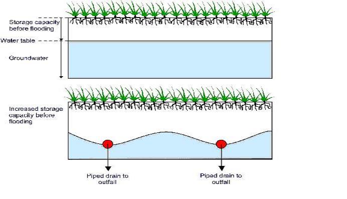 Figure 5 The effect on a groundwater table of the installation of piped drainage. Note that at the drain locality, the water table is lowered, increasing the capacity of the soil to store rainwater and reducing the frequency of flooding. Note also, how the water table rises in-between the drains – the height to which it rises is a function of the depth of drains and their spacing. If the drains are too shallow or too far apart, they can actually cause flooding – a common indication of poor drainage design
The infiltration rate (how quickly water enters the soil) is a function of many factors but is governed by the pore space in the soil – if the soil has an open structure at the surface water can flow into the soil easily; if the soil is capped or has small pores, the infiltration rate is reduced (Figure 7).
Low infiltration rate in sports surfaces is caused by:
- small pore sizes (eg. clay soils)
- compaction (wheeled traffic)
- capping (silts or sliding feet)
- some types of organic matter, including thatch
- or a combination of all of these.
The inability to get water into a sports surface is one of the most common land drainage issues and is known as a surface drainage problem.
 Figure 6 Typical infiltration rates for different soil media
Consideration of the above factors shows why clay soils are so susceptible to this problem – they have very small pores and the surface is easily smeared – providing a water tight seal over the soil. Installation of groundwater drains such as in Figure 5 will not solve this problem, the water cannot even get into the soil, let alone exit through the drains. If waterlogged and flooded pitches are to be avoided then it is necessary to bypass this impermeable surface completely using a surface drainage (or bypass) system. A surface drainage system uses bands of higher hydraulic conductivity / infiltration rate material to allow precipitation to bypass the low conductivity soil, straight from the surface to a piped drainage system. Such a scheme is detailed in Figure 8; the low conductivity soil (such as a heavy clay) has a very low infiltration rate and low hydraulic conductivity.
 Figure 7 The effect of particle size on infiltration rate: (a) coarse particles with wide pores allows water to infiltrate easily; (b) smaller particles with smaller pores restrict or prevent infiltration
In this system, some of the water from precipitation will pass slowly into the low conductivity soil – providing water to the grass plant. The majority of water, however, will flow across the surface and through the topdressing layer, into the vertical sand slits and then down into the collector drain and out to an outfall – completely bypassing the slowly permeable soil.
The system requires two key components for it to be effective:
- A high hydraulic conductivity connection to the surface – if a vertical slit becomes capped with fine textured soil, water cannot flow into the system and it will be redundant. For this reason it is necessary to provide frequent topdressing and careful devoting of the surface.
- An adequate collector drain network and outfall – if the water is not taken away, the material will become saturated rapidly and the system will not function.
1.4 Review of the key principles in selecting land drainage design
For the design of effective drainage in natural turf pitches the following points must be considered:
 Figure 8 A cross section and plan view of a sand slit system as an example of a surface or bypass drainage system for a low conductivity soil football pitch
- An investigation to determine whether the problem is caused by a water table (groundwater drainage) or a low infiltration rate (surface drainage).
- An investigation to determine the physical properties of the native soil.
- Determination of the correct depth and spacing for any piped drainage infrastructure.
- Calculation of the correct capacity for any infrastructure.
- Selection of hydraulically compatible and appropriate materials.
- Connection to free flowing outfall.
- Provision for hydraulic connection to the surface for bypass systems
Too many land drainage schemes fail because these points have not been addressed. The system must be designed to solve the problem in the field. As discussed above, the most common drainage problem is that of surface drainage in fine textured (clay) soils.
2 Sand Slit Drainage
If designed correctly and well maintained, sand slit drainage systems, such as the one illustrated in Figure 8, will reduce the risk of flooding and fixture cancellation.
The benefit of sand slit drainage systems A typical system of 1 m spaced sand slits (350 m deep) over a perpendicular lateral pipe network of 80 mm diameter drainage pipe (at a spacing of ~ 6 m and depth of 0.6 m) will provide sufficient drainage to prevent waterlogging in all but the most extreme conditions; with the proviso that such a system is regularly topdressed with a compatible sand. Over a period of years, prevention of revenue loss from fixture cancellation will offset the cost of installation and maintenance of a sand slit system. Less tangible benefits might include, improved reputation, the opportunity to stage higher profile fixtures – such as county tournaments etc, and improved training and youth development.
The sand slit system is highly effective and can be installed at a lower cost than a sand carpet system, where the complete pitch area is excavated and replaced with a purchased high sand content rootzone. The ongoing maintenance of sand slits is relatively cheaper and more straightforward than a sand carpet system too.
Investment in a sand slit and pipe drainage system that is regularly top-dressed will provide an effective land drainage scheme that will provide a direct, significant improvement to any facility where it is installed. As such, funding bodies can feel reassured that sand slit and pipe drainage will provide an effective return on investment (again, with the proviso that the facility in receipt has sufficient resources to both top up and topdress the system).
3 Mole drainage
3.1 The principles of mole drainage
Mole drainage is achieved by pulling a bullet-shaped plough through the soil to create a contiguous channel at depth. This channel provides a high hydraulic conductivity bypass conduit for water flow. The Cranfield University Mole Plough is shown in Figure 9. It is pulled through the soil at a depth of at least 400 mm, with a slight grade to encourage water flow.
 Figure 9 Cranfield University sports mole plough
As the plough is pulled through the soil, at approximately 1-2 m spacing, a vertical leg slot is formed, in addition a number of cracks are formed from the foot of the plough up to the surface as the soil is disturbed. These cracks form the principal bypass for water flow, connecting the surface to the mole channel (Figure 10). In agricultural, mole drainage surface heave is encouraged to help loosen the soil. In the drainage of sports surfaces, however, this is undesirable as surface disturbance upsets ball roll and can be a trip hazard.
There is a limited range of soil types that are suitable for mole drainage – essentially heavy, non-dispersive clay soils. The mole channel is cut by the foot, but formed by the expander. The expander forces displaced soil into the walls of the channel. In a sandy soil, the soil would simply collapse following the expander; in a clay soil, the soil is smeared and has sufficient cohesive strength to hold the channel open. As the channel dries it sets to form a hard walled channel, which can last anything from 5 to 10 years.
3.2 The benefit of mole drainage in sports fields
The benefit of this approach to drainage is cost – there are no materials required. The principal costs are labour, time, fuel and wearing of parts. There are reduced costs for drainage pipe and backfill material if a lateral collector system is required. As discussed above, however, the drainage scheme must be both low cost and drainage effective.
3.3 The cost of mole drainage in sports fields
A critical factor in the drainage of sports surfaces is the time taken to return to play following completion of works. With mole drainage there are three principal concerns:
- Surface disturbance
- Dangerous leg crack widths
- Durability and collapse of moles
Surface disturbance is caused by incorrect mole plough design, technique and soil conditions. Soil conditions are also responsible for short-lived moles too. Dangerous leg crack widths are a function of a soil property that affects clay soils and any drainage scheme. Due to the complex mineralogy of clay soils they exhibit shrink and swell properties. As the clay particles get wet they expand, as they dry out they shrink. This property causes the leg slot crack caused by the installation of the mole to expand as the soil dries through the summer – this expansion can reach a critical width whereby the risk of ankle joint or tendon injury is too high and fixtures are cancelled until the soil becomes wet and swells, closing the crack.
Careful consideration of the factors must be taken into account when installing mole drains. The critical requirements are the operating parameters – such as depth of installation, soil moisture content at installation and post installation management.
The article is an extract from the final report of a Football Foundation funded research project entitled The physical and financial benefits of mole drainage as an alternative to sand slitting in slowly permeable soils.
The research was conducted by:
Cranfield University www.cranfield.ac.uk/sas/staff/jamesi.htm
TurfTrax Ground Management Systems Ltd
www.turftraxgms.com
Should you have any further questions please do not hesitate to contact us